The TRASAR H Series High Power Slotted Array UHF Television Antenna offers broadcasters a flexibility in design coupled with high quality and proven performance. Computer aided design tools and anechoic chamber testing allow for custom solutions that meet your specific needs while allowing for optimization in tower design and coverage considerations.
- Antenna Theory Tutorial
- Antenna Basic Terms

- Types of Antennas
- Antenna Arrays
- Wave Propagation
- Antenna Theory Useful Resources
- Selected Reading
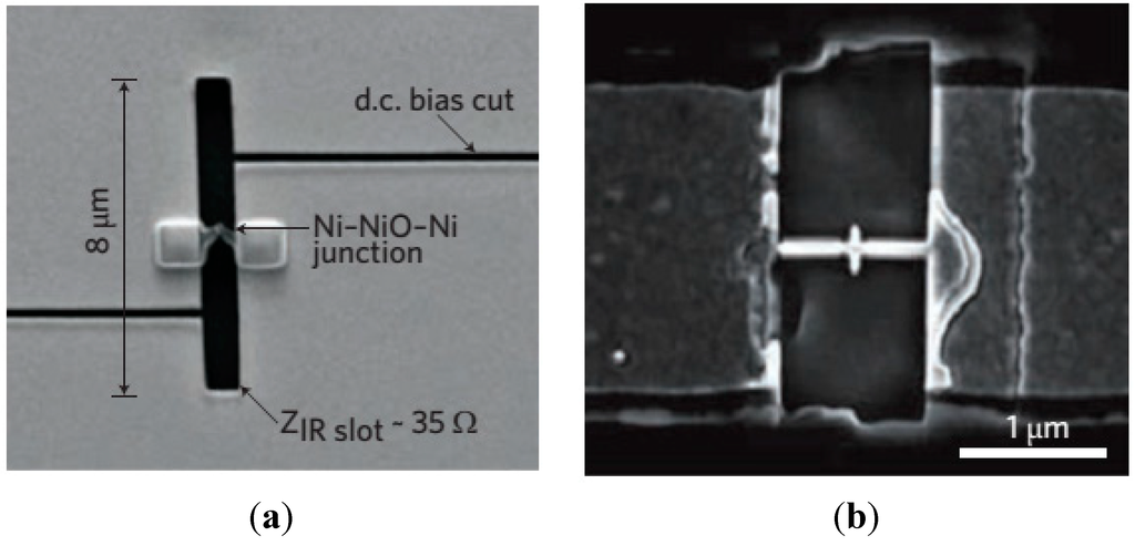
Slot Antenna is an example of Aperture antenna. A rectangular slot is made on the conducting sheet. These slot antennas can be formed by simply making a cut on the surface, where they are mounted on.
Frequency Range
The frequency range used for the application of Slot antenna is 300 MHz to 30 GHz. It works in UHF and SHF frequency ranges.
Construction & Working of Slot Antennas
The use of slot antennas is well understood through its working principle. Let us have a look at the structure of a slot antenna.
When an infinite conducting sheet is made a rectangular cut and the fields are excited in the aperture (which is called as a slot), it is termed as Slot antenna. This can be understood by observing the image of a slot antenna. The following image shows the model of a Slot antenna.
The working of Slot Antenna can be easily understood through Babinet’s principle of optics. This concept gives an introduction to the slot antennas.
Babinet’s Principle

Babinet’s principle states that- “When the field behind a screen with an opening is added to the field of a complementary structure, the sum is equal to the field when there is no screen”.
The above images clearly explain the principle. In all the regions, which are non-collinear with the beam, the above two screens, in figures 1 & 2, produce the same diffraction pattern.
Case 1 − Consider a light source and a conducting plane (field) with an aperture before a screen. The light does not pass through the opaque area, but passes through the aperture.
Case 2 − Consider the light source and a conducting plane of the size of the aperture in the previous case, being held against the screen. The light does not pass through the plane but through the remaining portion.
Case 3 − Combine these two conducting planes of both the cases and put before the light source. The screen is not placed to observe the resultant combination. The effect of screen gets nullified.
Working of Slot Antenna
This principle of optics is applied to electromagnetic waves for the wave to get radiated. It is true that when a HF field exists across a narrow slot in a conducting plane, the energy is radiated.
The image shows a slot antenna, which explains well about its working.
Consider an infinite plane conducting screen is taken and pierced with apertures of desired shape and size and this will be the screen of slot antenna. Another screen is considered interchanging the places of aperture and screen area which is the complementary screen.
These two screens are said to be complementary as they result in complete infinte metal screen. Now, this becomes the slot antenna. The terminal impedance is quite desirable for the radiation.
Radiation Pattern
The radiation pattern of the Slot antenna is Omni-directional, just like a half-wave dipole antenna. Take a look at the following illustration. It shows the radiation pattern of Slot antenna drawn in Horizontal and Vertical planes respectively
Advantages
The following are the advantages of Slot antenna −
- It can be fabricated and concealed within metallic objects
- It can provide covert communications with a small transmitter
Disadvantages
The following are the disadvantages of Slot antenna −
- Higher cross-polarization levels
- Lower radiation efficiency
Applications
The following are the applications of Slot antenna −
- Usually for radar navigational purposes
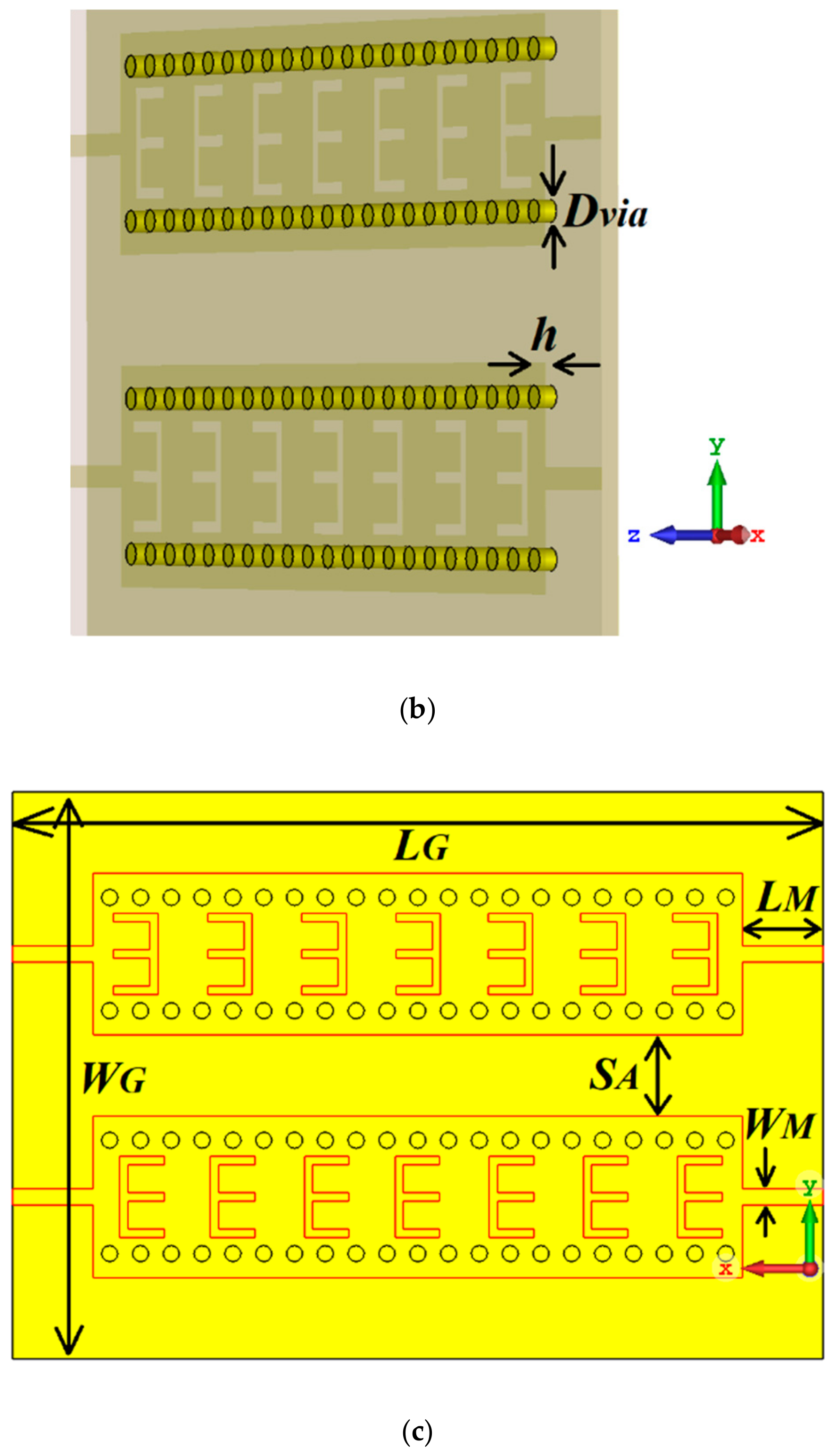
- Used as an array fed by a wave guide
Analysis of broad-wall slotted array waveguide for high frequency applications
This example shows how to analyze the performance of a slotted waveguide antenna.
Define parameters and Create a slotted waveguide
Longitudinal Linear Traveling Wave Slotted Waveguide

The array consists of radiating slots of different electrical lengths. Due to inherent property, each of them will resonate at their own individual resonance frequency. If the slot length and positions are chosen in such a way that the lower cut-off frequency and higher cut-off frequency of the nth slot overlaps with the higher and lower cut-off frequencies of the (n-1)th and (n+1)th slots respectively, then the complete array is expected to give a wide band response resulting in log-periodic dipole array. Slot Offset on broad wall slots are parallel to the waveguide centerline and they are blocking the transversal current components on the waveguide's broad wall. The polarization of these slots is vertical when the waveguide is held parallel to the ground and the transversal current component is zero on the centerline of the broad wall, however, if one slot moves closer to the narrow walls, the transversal current component increases. Therefore, the radiation amplitude of these slots increases as they move away from the centerline and that is why they are called offset slots. This is the most widely used slot type and this design is taken from [1].
Plot Reflection Coefficient
Plot the reflection coefficient for this antenna over the frequency band of 10GHz to 13GHz and a reference impedance of 50 ohms.
Radiation pattern
The most significant effect to be considered in the design process are internal and external mutual coupling between slots. The internal mutual couplings are caused by the partial reflections of the incident electromagnetic wave from succeeding slots in a waveguide. These partial reflections cause a considerable displacement of the EM field inside the waveguide.
Travelling Wave Antenna
Create custom slots in waveguide
a) Transverse Slots array
Transverse slots result in a very high value of their normalized resistance and they cannot be matched to the characteristic waveguide impedance. So, they have no practical importance.
b) X shape slots creation
The cross(X) slots can generate a circular polarized wave with a good axial ratio performance. The slots are oriented to form an orthogonal pair of slots which eventually generate a circular polarized wave. The theory of cross slots also suggests that the slots should be ideally equal to half of the free space wavelength.
Conclusion
The models of the Slotted waveguide antenna have been built and analyzed and agree well with results reported from [1].
References
1. Montesinos Ortego, 'Contribution to the design of waveguide fed compound slot arrays by means of equivalent circuit modeling'
Waveguide Slot Array Antennas
2. Zunnurain Ahmad,'Design and Implementation of Quasi Planar K-Band Array Antenna Based on Travelling Wave Structures'